
")
")
Process optimization (existing or new)
Example of proposed approach:
General principles: Use the 4 key parameters:
- Stiffnesses, as it controls static flexion and vibrations (if the stiffness is too low, chatter is unavoidable).
- Natural frequencies, because only the optimal spindle speeds make it possible to exploit the potential of the machining system (resonances must be avoided).
- Damping, because it is a factor aggravating the vibrations (if the damping is too weak, the vibrations are almost inevitable).
- Radial cutting force, because reducing radial force means reducing flexion and vibration.
Practical approach (3 days):
- Analysis of the machine-tool-part-part_holder system:
- Machine analysis: stiffnesses, natural modes (ping test), damping, accelerations/jerk/axis vibrations during G0 G1 G2 G3, spindle vibrations (over the entire speed range).
- Ping test of all major tools (heavily used tools, long and/or heavy tools, problematic tools).
- Process analysis: in-depth analysis of surface finish, analysis of machining vibrations, estimation or measurement of the radial component of the cutting force.
=> Identify the weak elements (spindle speed to avoid, insufficient stiffness or instability of a machine axis, damping of a workpiece holder, etc.), and determine the best spindle speeds for all major tools (also taking into account machine and tool limits).
=> Identify the phenomena to be combated (the machining signal clearly indicates runout, unbalance, intermittent cutting, resonances, more or less chaotic chatter).
=> Detect all factors that can be more productive (anytime machining is far from chatter)
=> Adapt the process to eliminate the problems detected (via speed adjustments or reductions in Ap Ae fz, depending on the type of problem), but also to increase wherever possible (↗Ap, ↗Ae, ↗fz), i.e. until the vibration signal detects the limits of the tool.
- Optimization of future process:
- Strengthen the weak parameters previously detected.
- Machine: recommendations of servo control adjustments or axis repair (with precise objectives).
- Workpiece holder: stiffening of part-holder, clamping systems, vacuum holders, etc.
- Tools:
- Stiffness : increase the body diameters, or shorten the lengths, or change the shrink fit, or change tool-holder.
- Resonance (i.e., natural frequency and damping) : optimal choice of rotational speed, damping improvement, optimal variable pitch, structural modification to change a natural frequency that is too annoying.
- Radial force : choice . reduction of radial effort via a choice of optimized cutting angles, helix angle, coatings, edge finish, but also by adjusting Ae.
- Tool by tool: determine the optimal parameters (N from ping test, Ap from raw calculation and from machining test, by seeking the limit of chatter minus margin of 20%, optimal Ae to reduce vibrations, fz to either reduce vibrations or at the limit of chatter -20% ), and reduce the number of operations as accurately as possible by calculating the actual chip thicknesses, taking into account the flexion, at each step (possibly using software to optimize the feed rate all along the path).
- Monitoring (to protect machine axis, monitor damage over time and anticipate vibrations of major tools, and continue to detect productivity sources) :
- Conventionally monitor the machine with no load (specific program to monitor spindle bearings, unbalances, etc.)
- Possibly monitor in more detail (specific programs to monitor motor currents, backlash, axis oscillations, etc.)
- Monitor during machining (to detect changes, or possible improvements, etc.): maximum acceleration threshold, frequency band threshold (spindle and axis protection), possibly by tool (detection of too violent interrupting cutting or chatter, for example)
Links
Our flyer : Services provided (pdf 2.9 Mo)
Machining vibrations on Wikipedia: https://en.wikipedia.org/wiki/Machining_vibrations
Some documents (see more link on the french version of this page):
Manufacturing Automation, Yusuf Altintas (2000)
Machining dynamics, Kay Cheng (2008)
Machining dynamics, Schmitz et Smith (2008)
Historical articles on machining vibrations:
On the art of cutting metal, Fred W. Taylor (1907)
Stability lobe theory, for milling, E. Budak, Y. Altintas (1995)
Variable pitch tools, E. Budak (2003)
(Do not hesitate to propose some other links)
Partners
University of Technology Tarbes Occitanie Pyrénnées, UTTOP
![]()
TechView - experts Inside, Supervision of machine tools
(ANDQO group)

Mecachrome group (one of the Vibraction co-founders is working there now)
Others experts, often working with us :
- For their sensors and diagnostic systems : IFM
![]()
- For their expertise on spindles : IBAG
- For their maintenance skills : AQMO

Providers :
- Brüel & Kjær (accelerometers) :![]()
- Viaxys (USB connection for accelerometers) :![]()
- Metil industries (dynamometer) :![]()
- Sauter (dynamometer) :![]()
- Mitutoyo (displacement sensor) :![]()
- Audacity Team (software ) :
Vibratory phenomenon (2)
Here we show some animations to help understanding of machining vibrations phenomenon
First, a machining vibrates all the time, but most of the time these vibrations decrease naturally. (see animation below)
Under certain conditions these vibrations can spontaneously accentuate. (see animation below)
All that depends on the passing tooth frequency and the vibration frequency multiplied by one or two or three, etc.
In the following animation, the passing tooth period is a little shorter than two periods of vibrations, the phenomenon is then unstable.
If the tooth passing period had been a little longer than two periods of vibrations, the phenomenon would have been stable, it is simple.
Most of the time, there is a simple rule to use : you have to machine with a tooth frequency slightly lower than the frequency of vibrations. Let us take an example :
Let us consider a 3 teeth tool that vibrates at 1000 Hz.
(you could measure that in a few minutes, very easily).
The rule is very simple :
The first coincidence frequency is : 1000/3 * 60 = 20 000 rev/min
The second frequency is : 1000/3 * 60 / 2 = 10 000 rev/min
The third : 1000/3 * 60 / 3 = 6666 rev/min
etc.
Optimal spindle speeds are a few percent lower than critical speeds, roughly : 19000, 9000, 6000 rev/min.
It is not more complicated than that, do not hesitate to contact us, we can demonstrate this on your own machining processes.
Softwares : MACHpro, CutPro, etc.
Your G-code programs can be automatically optimized using MACHpro software. It enables to predict x-y-z cutting forces, torque, tool flexion or workpiece, and vibrations :
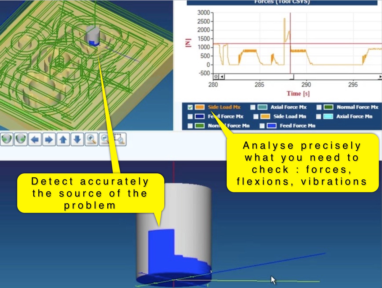
It is even enough simple to be used by CAD-CAM students, with such objectives as :
- Check that cutting forces are always acceptable for the machine (ex. 100 kg thrust force).
- Check that tool flexion is never too near of the surface precision needed (ex. 0.1 mm).
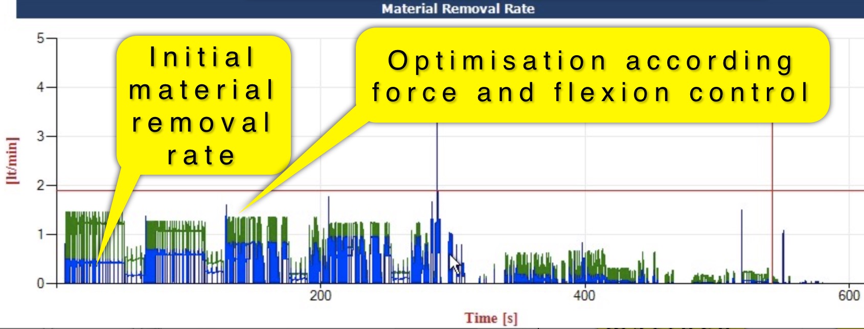
MACHpro can also modify automatically the G-code program to maximize the productivity, by changing the feed rate all along the path, regulating force (avoiding tool breakage) et flexion (avoiding bad dimensions), for example.
The removal rate is maximised by slowing down only the critical spots, automatically detected and regulated, and accelerating all the other zones where the machining tool may be used more efficiently.
For sophisticated machining, MACHpro is able to modelize any tool shape, including variable pitch tools, but also to modelize machine acceleration and jerk, etc. (forces are calculated including acceleration effects).
Production Module Software, from Third Wave System, is a good alternative to MachPro.
Page 1 of 2